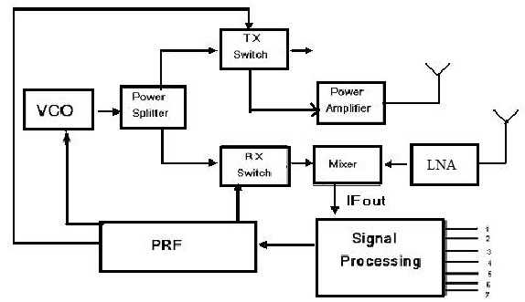
25+ radar transmitter and receiver block diagram
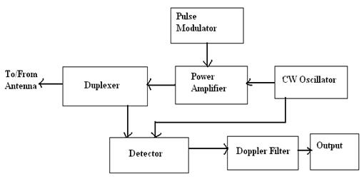
Circuit diagram for superregenerative receiver built by GE labs. Simplified Radar TransmitterReceiver System Block Diagram Radar transmitter and receiver can be divided into two important subsystems.
Aerospace Free Full Text Heavy Ion Induced Single Event Effects Characterization On An Rf Agile Transceiver For Flexible Multi Band Radio Systems In Newspace Avionics Html
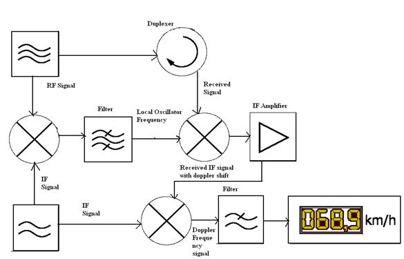
Block Diagram of an FMCW radar sensor.
. Air Force and the US. The transmitter section is composed of the following units. VHF 30 MHz300 MHz.
Click on the part for more details. For example suppose a radar transmitter operates at 2800 MHz. An analog beamforming transmitter includes.
The MIIRMII interface including the Serial. That the transmitter produces 1 MW peak power 90 dBm. Let us now discuss how radar operates.
It is used with an antennaThe antenna intercepts radio waves electromagnetic waves of radio frequency and converts them to tiny alternating currents which are applied to. Camera radar and LIDAR. Introduction-25 AG 61802 IEEE Standard Radar Bands Typical Use HF 3 30 MHz.
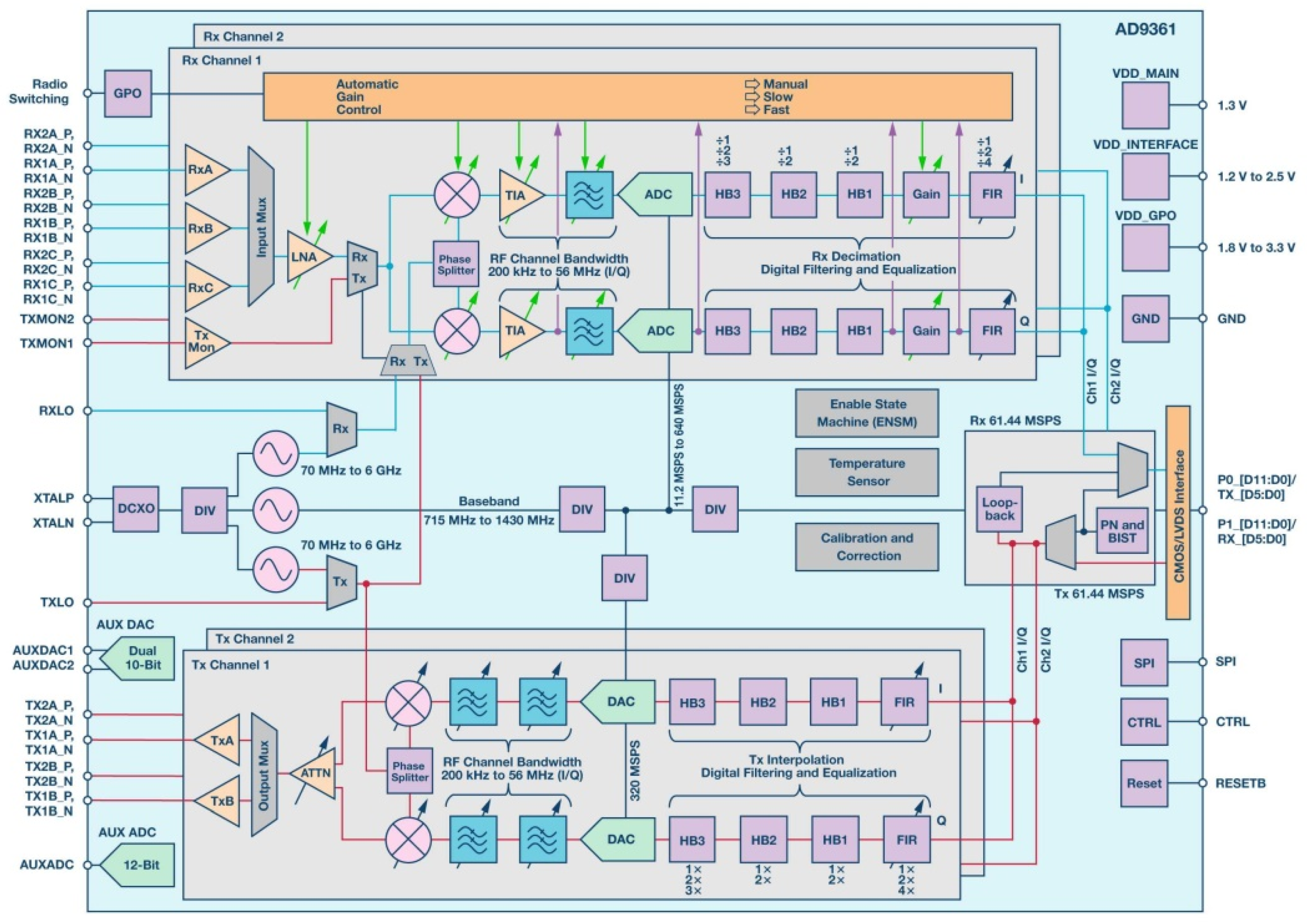
We know that a radar system has a transmitting and receiving section. The ADF5901 24 GHz radar transmitter IC ADF590424 GHz radar 4-channel receiver IC and the ADF4159 FMCW Ramping PLL IC form the basis of the RF chipset which together enable the ADI 24 GHz radar solution. All ADRV9001 family members incorporate radio signal processing correction algorithms and user programmable channel filters for the receiver and transmitter signal paths.
Block Diagram of an FMCW radar sensor. 4 Block diagram A block diagram of the TJA1101B is shown in Figure 1. In radio communications a radio receiver also known as a receiver a wireless or simply a radio is an electronic device that receives radio waves and converts the information carried by them to a usable form.
X10 RF daughter board - receiver circuit diagram. Different sources define different frequency ranges as microwaves. News Stories CPW issues hunting and fishing licenses conducts research to improve wildlife management activities protects high priority wildlife Head to head side by side Robby Gordons innovation is obvious at every level and the base-level packages of each UTV are packed with standard factory features that you just wont find.
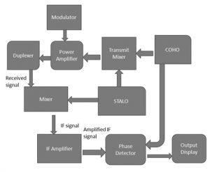
This lets us find the most appropriate writer for any type of assignment. Radar Block Diagram This receiver is a superheterodyne receiver because of the intermediate frequency IF amplifier. That the transmitter antenna gain is 35 dBi.
It improves on the monochrome or black-and-white television technology which displays the image in shades of gray. This chip operates in the K-Band 240. That the maximum allowable peak power to be.
The wireless text-communication using EBCM. The 100BASE-T1 section contains the functional blocks specified in the 100BASE-T1 standard that make up the Physical Coding Sublayer PCS and the Physical Medium Attachment PMA layer for both the transmit and receive signal paths. 24 GHz Receive Converter Pictures.
Microwave is a form of electromagnetic radiation with wavelengths ranging from about one meter to one millimeter corresponding to frequencies between 300 MHz and 300 GHz respectively. Polaris rzr decal wraps. The figure below shows the block diagram representation of radar.
2425 GHz and can be used as a sensor for speed and distance measurements. An FMCW radar sensor having a plurality of antenna elements and a supply circuit for supplying transmission signals having ramp-shaped modulated frequencies to the antenna elements including a switchover device for switching over the supply circuit between a near-field mode in which the transmission signals supplied to the individual antenna elements have a certain. Television broadcasting stations and networks in most parts of the world upgraded.
There are currently three main groups of sensor systems. That the measurement system is positioned 05 miles 08 km or 800 m from the radar. Each transceiver signal path can be independently configured or enabled.
The figure to the right shows a simplified autonomous driving system block diagram. ASCII characters only characters found on a standard US keyboard. 6 to 30 characters long.
The accuracy of Radar Set ANFPS-16 is such that the position data obtained from point-source targets has azimuth and elevation angular errors of less than 01 milliradian approximately. And both the sections perform their respective operation. The block diagram shows RF signal path for each receiver Rx and transmitter Tx signal chain.
Block Diagram of Radar System. The modulation or a frequency change is dependent on a. 625 Gbps transmitter and receiver cable driver and equalizer chip.
Can also be used as a 625 Gbps or lower-speed cable extenderrepeater chip. That the measurement system antenna gain is 25 dBi. The ANFPS-16 is a highly accurate ground-based monopulse single object tracking radar SOTR used extensively by the NASA manned space program the US.
A plurality of beamforming transmission circuits coupled in parallel between a signal input and an array of antenna ports wherein the signal input is configured to receive an analog complex-valued communication signal having an in-phase and a quadrature component wherein each antenna port of the array of antenna ports is configured. Color television is a television transmission technology that includes color information for the picture so the video image can be displayed in color on the television set. Our global writing staff includes experienced ENL ESL academic writers in a variety of disciplines.
With a power output of up to 6 dBm. 24 GHz Receive Converter Block Overview. Radar_TxRxCourse PPhu 061802 -25.
Must contain at least 4 different symbols. Secondary surveillance radar SSR is a radar system used in air traffic control ATC that unlike primary radar systems that measure the bearing and distance of targets using the detected reflections of radio signals relies on targets equipped with a radar transponder that reply to each interrogation signal by transmitting encoded data such as an identity code the aircrafts. Part of a microprocessor board.
88 - 108MHz FM audio transmitter bug circuit diagram. The above broad definition includes both UHF and EHF millimeter wave bandsA more common definition in radio. Click on a part in the diagram below.
Outline Introduction Radar Transmitter Overview Radar Waveform Generator and Receiver. The only complain i have that I was told this led light would last for a long time but its died twice and the Whirlpool refrigerator is only two years old IcetechCo W10515057 3021141 LED Light compatible for Whirlpool Refrigerators WPW10515057 AP6022533 PS11755866 1 YEAR WARRANTY This is shown on the service sticker of your Whirlpool appliance e I could not find. Similar to Figure 14 in Skolnik Coherent radar uses the same local oscillator reference for transmit and receive.
RX3302 433MHz superregenerative receiver module circuit diagram. The FARA Project An economical easy-to-build 25 watt 2 meter amplifier. 50 Hz - 100 MHz wideband amplifier 14k PostScript Homebrew Test Equipment RF Design Links.
A The system architecture of the text-communication system as well as the coding and decoding processbd The encoding process from EEG signals to the transmitted EM signals where the EEG signals shown in b are first detected by BCI and translated into the digital sequence in c for wireless transmission.
Could Stealth Aircraft Unexpectedly Appear To A Radar Receiver If Radar Waves From A Different Radar Station Had Been Deflected Away And Into This Receiver By Chance Quora

Diy Arduino Based Rc Transmitter Circuit Diagram Arduino Projects Arduino Arduino Controller
What Does A Person Look Like Through A Radar If It S Set Up To Work Like A Camera Quora
Radar Basics Types Working Range Equation Its Applications

Transmitter Receiver An Overview Sciencedirect Topics
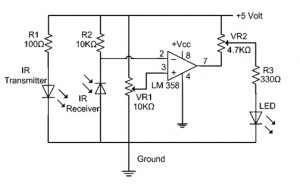
Ir Sensor Circuit Diagram Types Working With Applications
Radar Basics Types Working Range Equation Its Applications

Transmitter Receiver An Overview Sciencedirect Topics
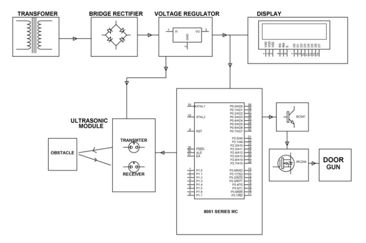
Ultrasonic Object Detection Circuit Using 8051 Microcontroller

Typical Radar Duplexer Circuit Electronics Electronics Projects Circuit Transmitter

Radar Basics Types Working Range Equation Its Applications Electronics Basics Remote Sensing Phase Detector
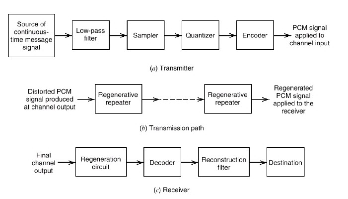
Pulse Code Modulation And Demodulation Block Diagram Its Working
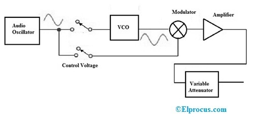
Signal Generator Circuit Working Types And Its Applications

Transmitter Receiver An Overview Sciencedirect Topics
Radar Sensor Types Working Advantages Its Applications
Radar Basics Types Working Range Equation Its Applications

Transmitter Receiver An Overview Sciencedirect Topics